E78-LN Series, LoRaWAN module E78-868LN22S(6601)
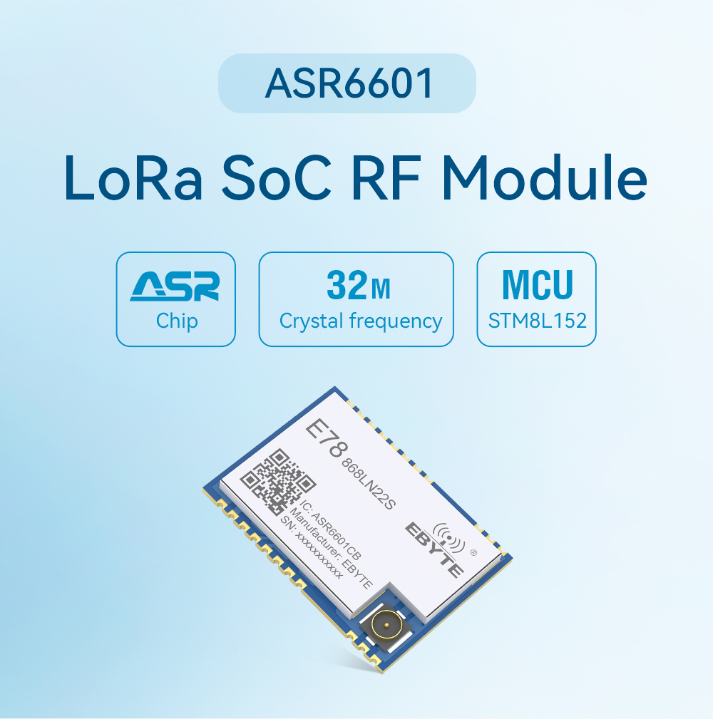
E78-868LN22S(6601)
[IC]:ASR6601
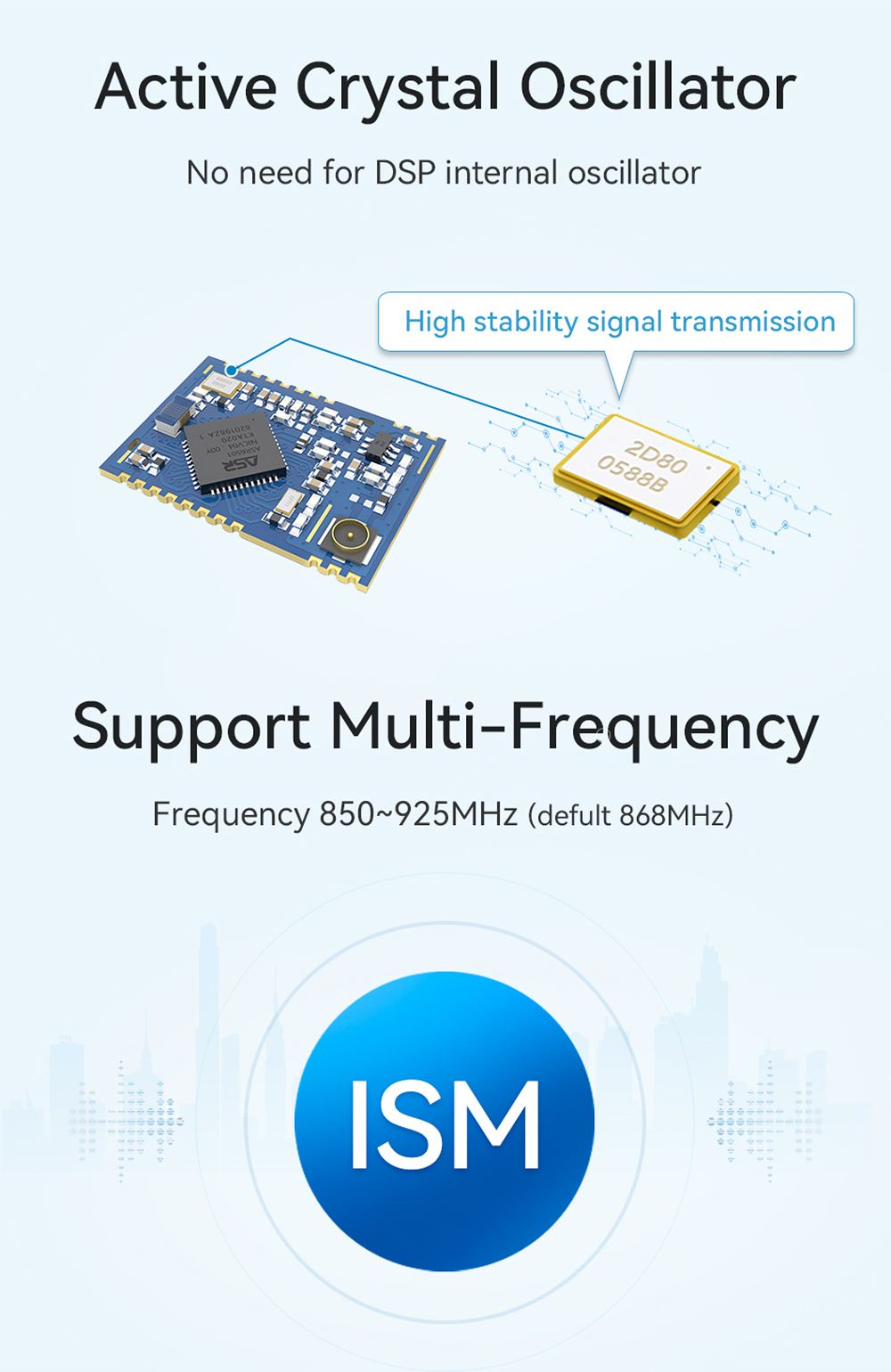
[Frequency]:850~925MHz
[Power]:21dBm
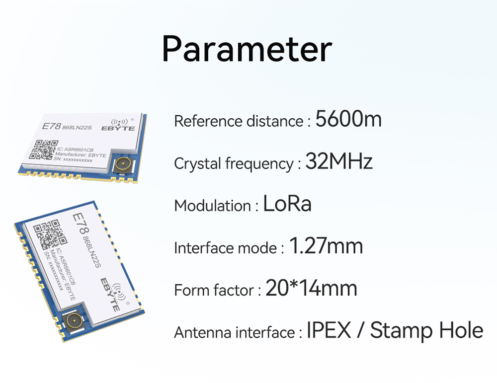
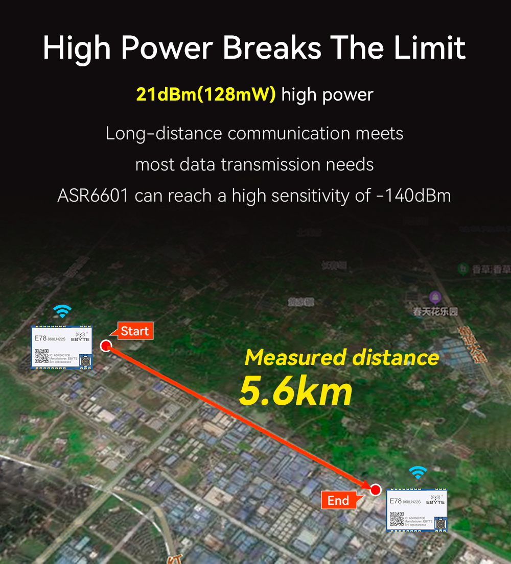
[Distance]:5.6km
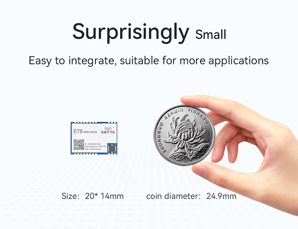
[Size]:14*20mm
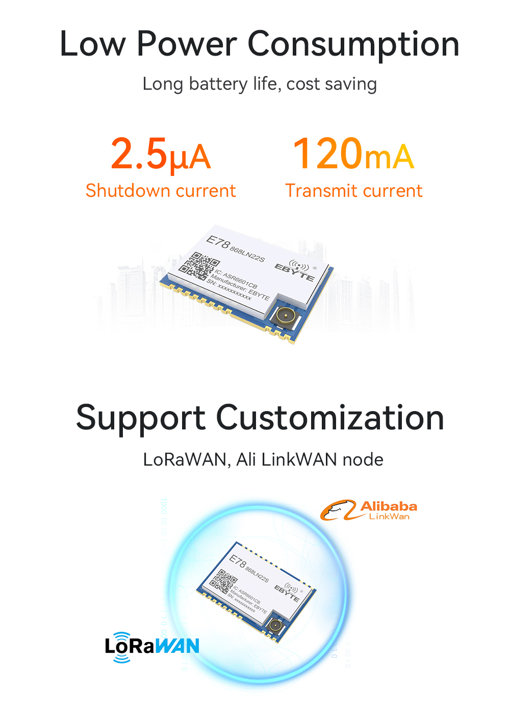
[Introduction]:E78-868LN22S (6601) series of products is the Chengdu EBYTE Electronic Technology Co., Ltd. design and production of the standard LoraWan node module, operating band EU863 to 870MHz, support CLASS - A/CLASS-C node type.
| Model | Interface | IC | Frequency Hz | Power dBm | Distance km | Air Rate(bps) | Package | Size (mm) | Feature | Manual |
| E78-470LN22S | - | ASR6501 | 433M | 22 | 7,0 | 0.018k~62.5k | SMD | 14*20 | Low consumption, anti-interference | ✔ |
| E78-868LN22S(6601) | SoC | ASR6601 | 868M | 22 | 5,6 | 0.018~62.5k | SMD | 14*20 | standard LoRaWan node module | ✔ |
| Main Parameter | Description |
Remark |
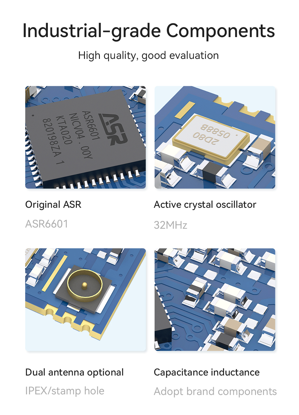
| IC |
ASR6601CB |
- |
| Form factor |
20* 14*2.8 mm |
- |
| Weight |
1.2±0.1g |
- |
| Operating temperature |
-40 ~ 85℃ |
- |
| Working temperature |
10% ~ 90% |
- |
| Storage temperature |
-40 ~ 125°C |
- |
|
Emission current(Lora@2.4kbps) |
110~130mA |
- |
|
Receive current(Lora@2.4kbps) |
13~15mA |
- |
| Turn off the current |
2.4~2.6μA |
- |
| Transmit power |
21dBm |
- |
| Receive sensitivity |
-139~-140dBm |
- |
| TCXO crystal |
32MHz |
- |
| TCXO crystal voltage configuration |
1.8~3.3V |
- |
| Recommended operating band |
850~925MHz |
- |
| Reference distance |
5600m |
Clear and open, antenna height 2 meters, air rate 1kbps |
| Crystal frequency |
32MHz |
- |
| Modulation |
LoRa |
GFSK Mode ,FLRC Mode,LoRa Mode |
| Package |
SMD |
- |
| Interface mode |
1.27mm |
- |
| The communication interface |
SPI |
0~10Mbps |
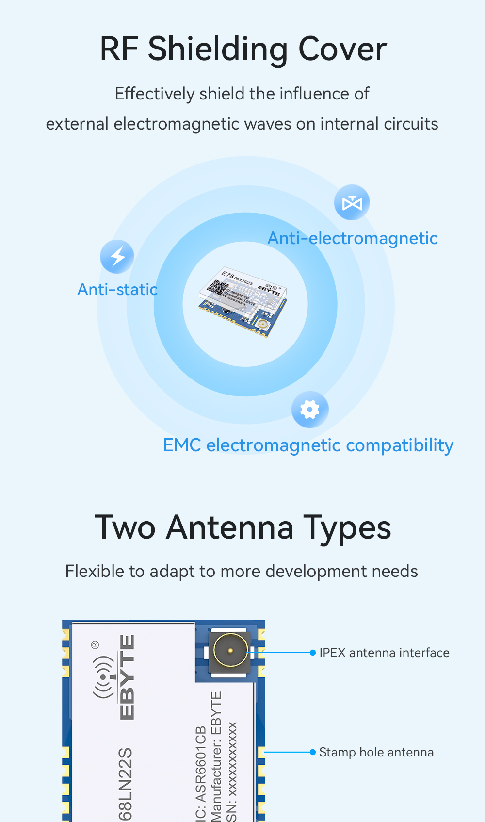
| Antenna interface |
IPEX/stamp hole |
with an equivalent impedance of about 50Ω |


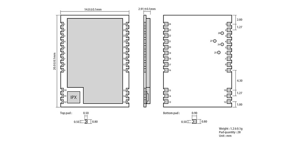
| No. |
Pin Name | Pin direction | Pin use |
| 1 | GND | - |
ground wire, connected to the power reference |
| 2 | VCC |
- |
Power supply, range 2.5V to 3.7V(ceramic filter capacitor is recommended externally) |
| 3 | SETB |
- |
Wake-up pins with low power |
| 4 | DIO1 |
Input/output |
NC(reserve pin) |
| 5 | BUSY |
Input/output |
NC(reserve pin) |
| 6 | I2C_SDA |
Input/output |
NC(reserve pin) |
| 7 | I2C_SCL |
Input/output |
NC(reserve pin) |
| 8 | UART_CTS |
Input/output |
NC(reserve pin) |
| 9 | UART_RTS |
Input/output |
NC(reserve pin) |
| 10 | GND | - |
ground wire, connected to the power reference |
| 11 | ANT |
- |
Antenna interface, stamp hole(50 ohm characteristic impedance) |
| 12 | GND | - |
ground wire, connected to the power reference |
| 13 | GND |
- |
ground wire, connected to the power reference |
| 14 | GND |
- |
ground wire, connected to the power reference |
| 15 | GND |
- |
ground wire, connected to the power reference |
| 16 | XRES |
Input |
The external reset pin |
| 17 | ADC_IN |
Input |
NC(reserve pin) |
| 18 | AUX |
Input/output |
NC(reserve pin) |
| 19 | SETA |
Input/output |
NC(reserve pin) |
| 20 | UART_RX |
Input/output |
UART RX pin |
| 21 | UART_TX |
Input/output |
UART TX pin |
| 22 | SWD_DATA |
Input/output |
SWD Data pin |
| 23 | SWD_CLK |
Input/output |
SWD Clock pin |
| 24 | GND | - |
ground wire, connected to the power reference |
| 25 | SPI_MISO |
Input/output |
The SPI MISO test point, which is internally connected and cannot be used as an external SPI |
| 26 | SPI_NSS |
Input/output |
The SPI NSS test point, which is internally connected and cannot be used as an external SPI |
| 27 | SPI_MOSI |
Input/output |
The SPI MOSI test point, which is internally connected and cannot be used as an external SPI |
| 28 | SPI_SCK |
Input/output |
The SPI SCK test point, which is internally connected,cannot be used as an external SPI |